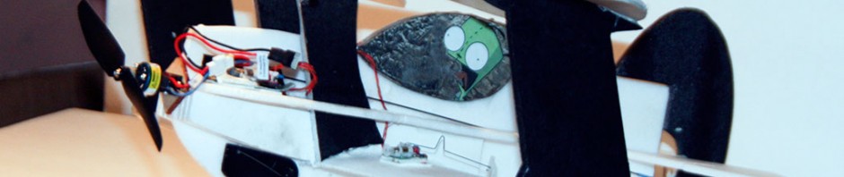
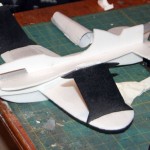
Based on the “Bipie” plans from RCGroups, this little guy will have an 18″ wingspan and be built from a single sheet of Dollar Tree foam board.
I’m hoping to use the guts from an E-flite UMX Gee Bee to power the whole thing.
Planned AUW is in the ballpark of 100 – 120 grams.
I’m pulling the paper off of the wings, then adding a single layer of very light fiberglass to the bottoms. The interplane and cabane struts will definitely be keeping their paper.
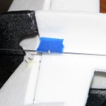
One problem I hadn’t really thought about was the plans, which are glued to the foamboard. I can’t take the paper plans off of the struts without removing all the paper, so I’ll somehow have to cover up the clearly visible lines and words. (Paint? Marker? Tape?)
I am pretty sure that the fuselage will be losing its paper. I want to keep the weight down as far as possible. I pulled the paper off the fuselage, to keep the weight down as far as possible. It got pretty floppy and I was worried, but the fuselage supports stiffened things up pretty well.
Another problem was the push rods. Since I’m using the UMX Gee Bee brick, I’m limited to very thin wire for the push rods. This wire is way to thin and flexes way too much when run all the way back to the rudder and elevator. I fashioned new push rods from 0.040″ CF rod, 1/16″ shrink tubing, and CA.
-
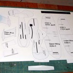
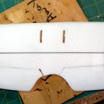
- Printed plans, glued to a sheet of foamboard
-
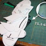
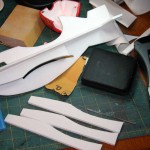
- Parts cut and weighed
-
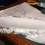
- Bottom wing, glassed
-
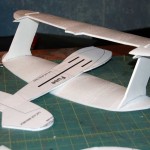
- Dry fit of the wings
-

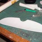
- Aileron cut from top wing
-
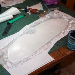
- Top wing, glassed
-
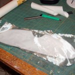
- Top wing, paperless
-
- Getting ready for ‘glassing
-
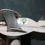
- Motor mount position test
-
- A quick test fit
-
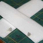
- Fuselage supports – 3 on each side
-
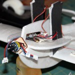
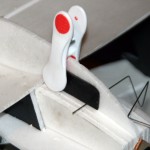
- Gluing the motor mount in place
-
- Aileron servos mounted and hooked up
-
- Left aileron servo, hooked up
-

- The ever-growing To Do list
-
- Gee Bee aileron control horns, transplanted
-
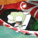
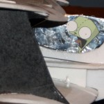
- Creating a shiny canopy
-
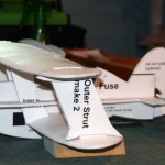
- Interplane struts, painted black
-
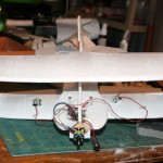
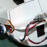
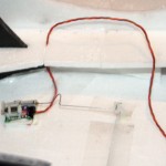
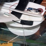
- Electronics test installation
-
- Cockpit and pilot in place
-
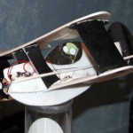
- Everything glued in place and ready to test
-
- Marking CF push rod to cut to length
-
- New push rod
-
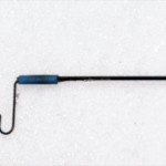
- A close-up of one push rod end
-
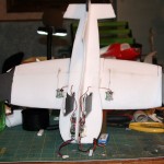
- All built and awaiting landing gear
-
- Attaching the landing gear mount
-
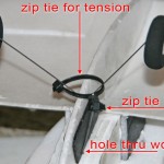
- Landing gear wire zip-tied in place
-
- Landing gear construction
-
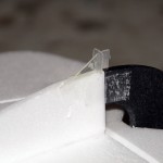
- Tail skid (upside down)
-
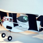
- Ready for maiden
-
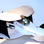
- Another view
-
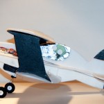
- Yet another view
Pingback: [BLOCKED BY STBV] Computing Surface area with Photoshop | Basement R/C